
 English
 русский
 عربى
عربىتلتزم آلات Xinliang دائمًا بفلسفة الأعمال "الموجهين نحو الأشخاص ، العميل أولاً ، الإدارة الصادقة ، والتعاون الفائز بالجانبين".
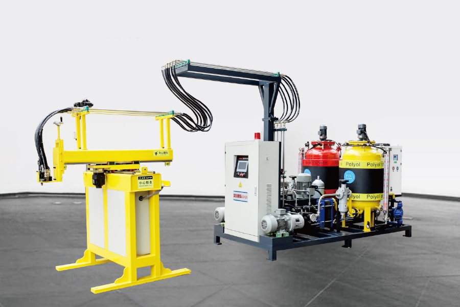
من خلال التحكم في محرك المؤازرة ، باستخدام معالج ثلاثي المحاور ، وبرمجة البرنامج ، والاندماج مع معدا...
انظر التفاصيلIn automotive seat manufacturing, the precision and consistency of polyurethane (PU) foaming directly impact ride comfort and safety. Traditional manual injection methods suffer from uneven filling and large density fluctuations. However, a six-axis robot-integrated high-pressure foaming machine, by precisely controlling the trajectory and process parameters, can increase the foam molding pass rate to over 99%. How does a six-axis robot-integrated two-component polyurethane high-pressure foaming machine achieve precise PU foaming for automotive seats?
محتوى
Incomplete Filling: Complex curved surfaces are prone to bubbles or cavities.
Uneven Density: Fluctuations in manual injection speed can result in foam hardness variations exceeding 15%.
Raw Material Waste: Overfilling or leaks can result in up to 20% raw material loss.
|
Specifications |
Manual Foaming |
Robot + High-Pressure Foaming Machine |
|
Injection Accuracy |
±10% |
±1% |
|
Repeatability |
5mm |
0.1mm |
|
Production Cycle |
3-5 minutes/piece |
1-2 minutes/piece |
|
Quality Rate |
85%-90% |
≥99% |
Symptoms:
Uneven mixing of components A and B, resulting in streaky foam
Abnormally high injection pressure (>250 bar)
Sudden decrease in discharge volume
Solution:
Immediately shut down the machine, switch to cleaning mode, and flush the mixing chamber with a dedicated cleaning agent.
Disassemble the mixing head for inspection:
Remove solidified material residue (use a copper brush; avoid scraping with hard metal objects).
Check for wear on the dynamic mixer (standard clearance 0.1-0.3 mm).
Preventative Measures:
Perform the automatic flushing procedure (at least 30 seconds) after each shutdown.
Replace the filter element monthly (precision ≤ 50 μm).
Symptoms:
Foam is brittle (too much component A) or soft (too much component B)
Flowmeter indicates a >5% difference between components A and B
Solution:
Calibrate metering pumps:
Test the output of components A and B individually (error should be <1%)
Adjust gear pump speed compensation
Inspect raw materials:
Measure the moisture content of isocyanate (component B) (should be <0.05%)
Preheat raw materials to 35±2°C (temperature affects viscosity)
System Verification:
Perform a static mixing test (measure density after sample curing)
Symptom:
Injection path deviates from mold cavity
TCP (Tool Center Point) positioning error > 2mm
Solution:
Recalibrate TCP:
Use the three-point method to calibrate the nozzle center position
Verify the zero position of each axis (requires a dedicated laser tracker)
Check mechanical structure:
Check harmonic reducer backlash (allowable value < 0.1°)
Adjust balance cylinder air pressure (standard 0.5-0.6 MPa)
Program optimization:
Segmented deceleration for complex paths (corner speed reduced to 70%)
Symptom:
Robot suddenly stops and reports an error
Axis 4/5 approaches coaxial state
Solution:
Path replanning:
Avoid singularity areas in the offline programming software
Add transition points to change posture
Parameter adjustment:
Reduce speed when approaching singularity points (< 50% rated speed)
Enable joint soft limit protection
Symptoms:
Voids with a diameter > 3mm appear in the foam cross-section
Local density variation > 15%
Solution:
Process Adjustment:
Increase injection pressure (recommended 150-200 bar)
Extend curing time (adjust based on ambient humidity)
Mold Optimization:
Add venting grooves (area ≥ 15%)
Preheat the mold to 40-45°C
Raw Material Processing:
Vacuum degassing pretreatment (vacuum degree ≤ -0.095 MPa)
Symptoms:
Uneven texture on the foam surface
Uneven gloss
Solution:
Parameter Optimization:
Reduce injection speed (80% of the standard value)
Adjust the temperature difference between components A and B (recommended ΔT < 3°C)
Equipment Maintenance:
Clean all raw material lines (acid wash once a month)
Check the response time of the pressure regulating valve (should be < 0.5 seconds)
Symptoms:
Pressure curve fluctuates in a jagged pattern (amplitude > ±10 bar)
Metering motor frequently adjusts speed
Solution:
Check the hydraulic system:
Replenish accumulator nitrogen pressure (pre-charge pressure = system pressure x 0.8)
Replace the pulsation damper (recommended service life: 2000 hours)
Electrical inspection:
Tune servo driver PID parameters (increase integration time)
Calibrate the pressure sensor (verify 4-20mA signal)
Symptoms:
The robot controller loses connection with the foaming machine PLC
HMI displays "Communication Error"
Solution:
Hardware inspection:
Test the Profinet/DeviceNet connector impedance (should be <100Ω)
Replace the fiber optic module (if a flashing red light appears, an alarm will sound)
Software solution:
Reset the master and slave configurations
Update the firmware (pay attention to compatibility)
Symptom:
Isocyanate leaking from pipe joints
Pungent odor in the workshop
Solution:
Emergency measures:
Immediately activate the exhaust system (air velocity ≥ 0.5 m/s)
Treat the leak with a dedicated neutralizer (such as ammonia solution)
System improvements:
Replace compression fittings with welded ones
Add pressure decay detection (sensitivity 0.5 bar/min)
Symptom:
Equipment does not completely stop after pressing the emergency stop button
Safety circuit not disconnected
Solution:
Safety checks:
Test all emergency stop series contacts (resistance should be <1 Ω)
Check safety relay status (verify with LED indicator)
Maintenance procedures:
Test the emergency stop function monthly (record response time)
Replace buttons that have reached the end of their life (recommended cycle: 3 years)
The six-axis robot two-component polyurethane high-pressure foaming system is a precision device that integrates mechanical, hydraulic, electrical, and chemical processes. Standardized maintenance ensures:
Foaming accuracy within ±1%
Equipment life extended to 8-10 years
Raw material utilization increased to over 98%
Safety incident rate reduced by 90%
Pre-Startup Inspection
Hydraulic System:
Oil tank level (2/3 of the sight glass)
Pressure gauge zeroed
Accumulator pressure (Nitrogen pre-charge pressure = operating pressure x 0.8)
Raw Material System:
A/B component temperature (35 ± 2°C)
Raw material tank level (>30%)
Filter pressure differential (<1.5 bar)
Post-Shutdown Maintenance
Perform a 3-minute automatic flushing cycle
Clean the mixing head (with a dedicated copper tool)
Remove polyurethane residue from the equipment surface
Daily Cleaning:
Solvent Flush Pressure > 5 bar
Flush Time ≥ 30 seconds
Deep Cleaning:
Ultrasonic Cleaning (40 kHz Frequency, 15 minutes)
Nozzle Orifice Inspection (Replace if wear > 0.1 mm)
Seal Replacement
Disassembly Procedure:
Release hydraulic pressure
Remove 8 M6 hexagon socket bolts
Remove old seal (do not use sharp tools)
Installation Tips:
Soak new seal in lubricant for 30 minutes
Tighten bolts crosswise (torque 12 N·m)
Grease Replacement:
Drain old grease (until new grease overflows)
Grease Injection Pressure < 3 bar
Wear Inspection:
Backlash Test (allowable value < 0.1°)
Vibration Test (< 4.5 mm/s)
Servo Motor Maintenance
Insulation Test:
Winding-to-ground resistance > 100 MΩ
Phase Balance < 5%
Encoder Inspection:
Clean the optical window
Check cable connections
من خلال التحكم في محرك المؤازرة ، باستخدام معالج ثلاثي المحاور ، وبرمجة البرنامج ، والاندماج مع معدا...
انظر التفاصيل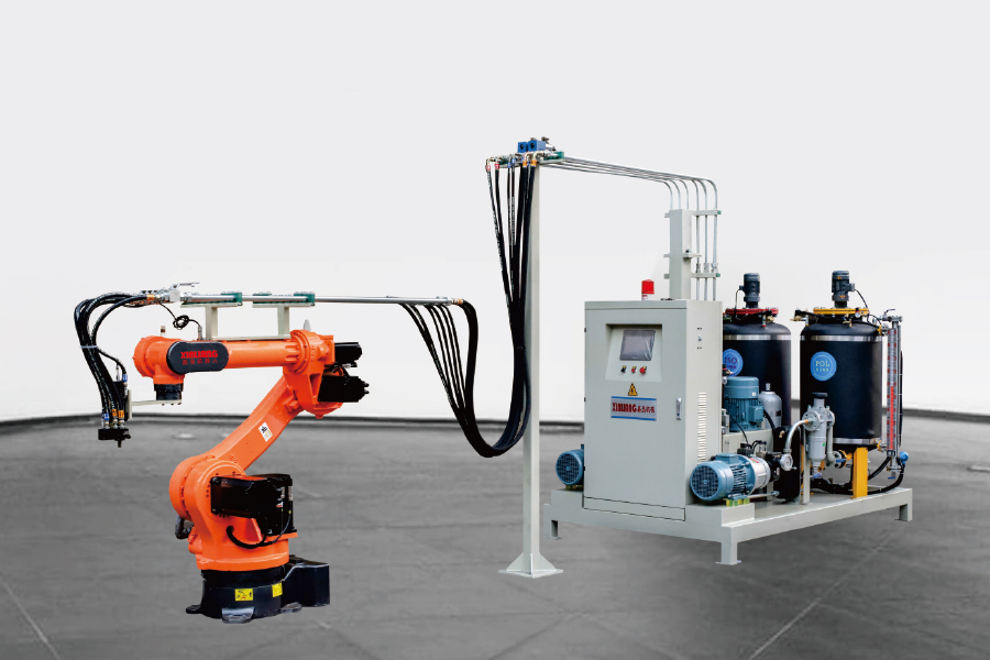
يمكن تخصيص العلامة التجارية الروبوت ، ويتم استخدام المعالج المكون من ستة محاور. إنه مناسب للجمع ب...
انظر التفاصيل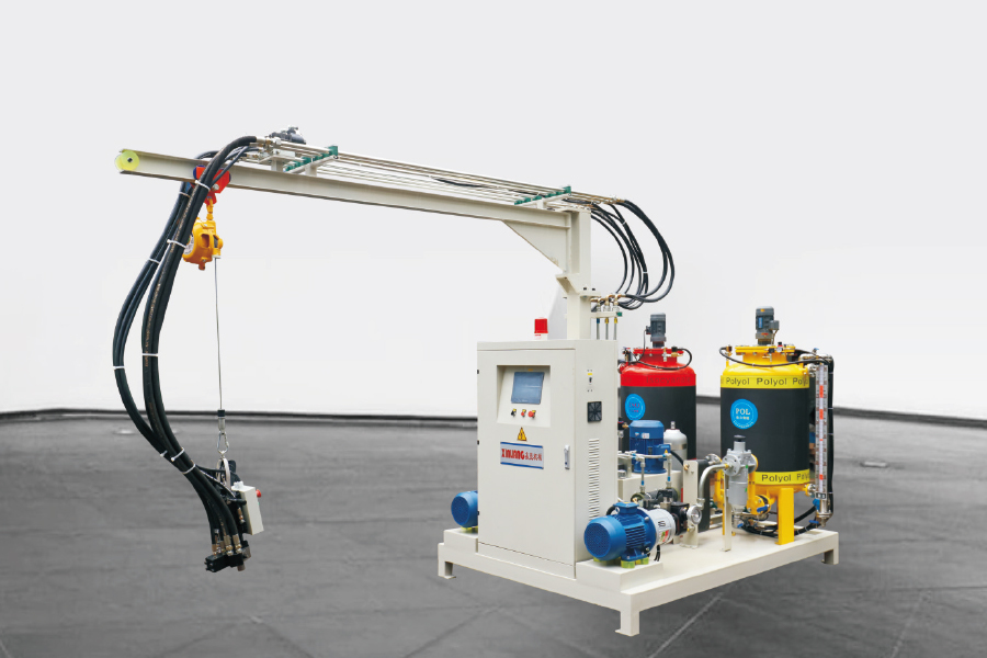
تستخدم آلة حقن البولي يوريثان عالية الضغط عالي الضغط ذراع الروك لحقن الدوران 180 درجة. يمكن تخصيص...
انظر التفاصيل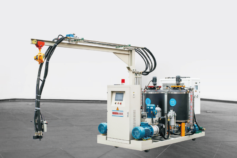
يحتوي آلة حقن الرغوة ذات الضغط العالي المكون من المكونات ذات المكون المكون مع المسار على نفس التك...
انظر التفاصيل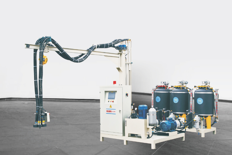
تحتوي آلة حقن الرغوة ذات الضغط العالي المكون من ثلاثة مكونات على خزان ISO 1 و 2 خزانات بولي. يمكن...
انظر التفاصيل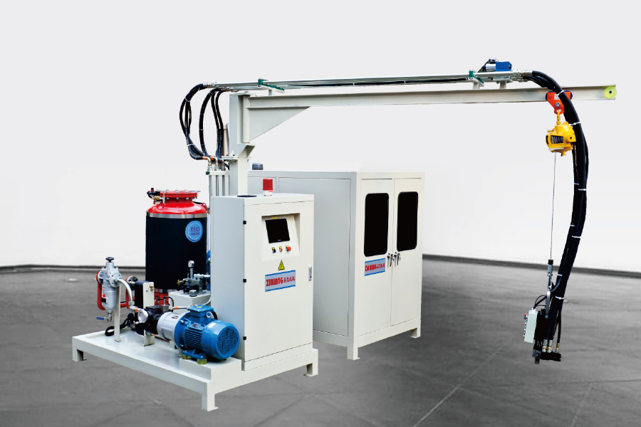
سيكلوبنتان البولي يوريثان ، آلة حقن الرغوة عالية الضغط يعني أن بولي يحتوي على السيكلوبنتان. المواد ا...
انظر التفاصيل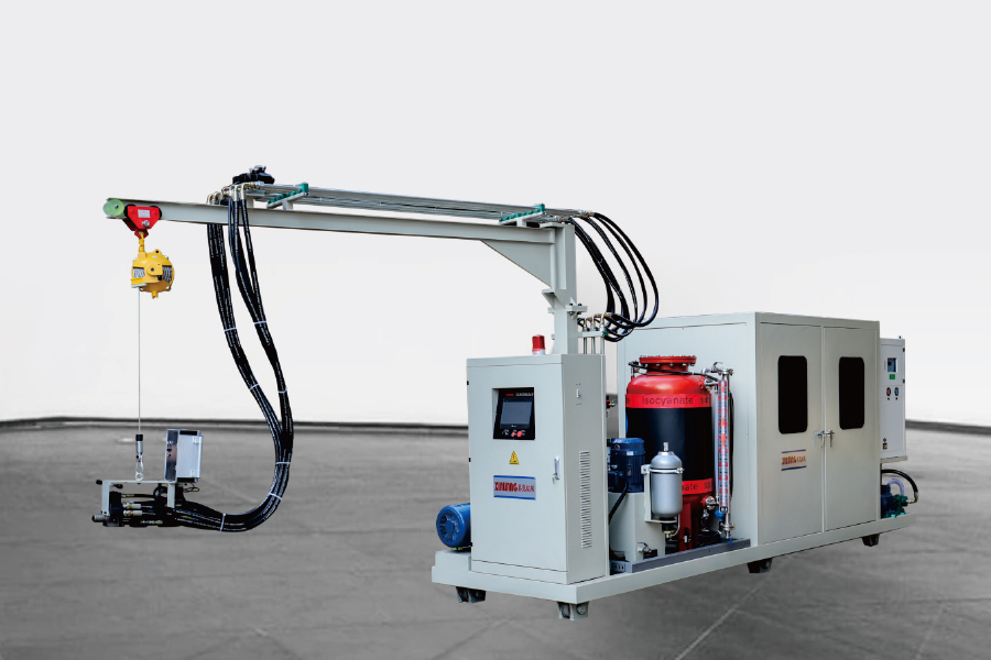
التكوين هو نفس آلة الرغوة ذات الضغط العالي السيكلوبنتان. الفرق الوحيد هو أنه بالنسبة لبعض مصانع العم...
انظر التفاصيل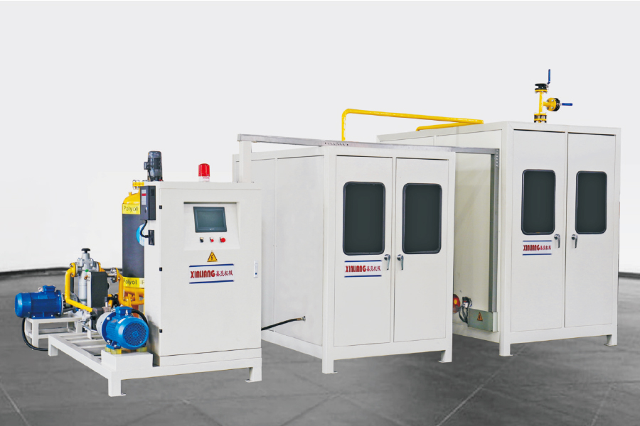
مبدأ العمل لنظام Cyclopentane Premixing قياس وخلط مختلف المواد الخام البولي يوريثان ، مثل الإيزوسيان...
انظر التفاصيلحقوق الطبع والنشر © Ningbo Xinliang Machinery Co. ، Ltd. جميع الحقوق محفوظة.
